Quick Start

Your Remal IoT development board is a tool that will open up endless possibilities for you to explore and develop your skills. We can’t wait to see what you create with it! If you run into any issues or have any questions, don’t hesitate to reach out to us. We’re always ready to help and make sure you’re getting the most out of your new board. Keep on creating, and thanks again for choosing us!

Note: If you’ve added any Remal IoT boards to your Arduino IDE before July 29 ’23, we kindly ask you to:

  1. Uninstall all Remal boards from the Boards Manager
  2. Remove and re-add the board link in Preferences: “https://remal.io/remal-core/package_remalboards_index.json”
  3. Redownload Nabd and Atlas (AVR) v1.2.7+ or Shabakah (ESP32) v1.2.1+

This refresh fixes a file path issue and ensures you get all our future updates. We apologize for the inconvenience!

Installing the Arduino IDE and Adding Remal Boards

Using the Arduino IDE is a great way to write and upload code for boards that support the Arduino framework. It has a user-friendly interface, sample sketches, and a library manager to easily download additional libraries. It’s also open-source, regularly updated with new features, and has a large community of users who can provide support and share their own projects and experiences. This is why we here at Remal IoT made sure all our boards support the Arduino IDE. Adding Remal boards to the Arduino IDE is simple and quick:
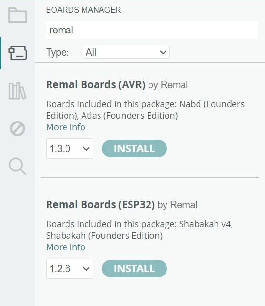
  1. First, you will need to download the latest Arduino IDE from the Arduino website and choose the version that matches your operating system
  2. To add boards to the Arduino IDE, open the Arduino IDE and go to “File > Preferences”
  3. In the Additional Boards Manager URLs field, enter:

    https://remal.io/remal-core/package_remalboards_index.json

  4. Click OK to save your changes
  5. Go to “Tools > Board > Boards Manager” and search for “remal iot”:
  6. Click install on both or depending on which Remal IoT board you own

And that’s it! Once the board is installed, you can select it from the “Tools > Board” menu. Happy coding!

Shabakah

Shabakah Pinout Diagram

Shabakah is powered by Espressif Systems ESP32-C3-MINI. It is an extremely capable microcontroller with a lot of customizability regarding pin functionalities. We highly encourage users to check out these resources to get the most out of their Shabakah board:

  • Learn more about Shabakah here! Don’t forget to check out the “Block Diagram” and “Documents” tabs while you’re there!
  • Arduino Language Reference – Learn about the Arduino language here
  • ESP32 Libraries – Find ESP32’s unique Arduino functions and APIs here
  • Arduino ESP32 – Great resource to learn more about ESP32 and Arduino


Shabakah Example Code

Every Shabakah board comes pre-flashed with demo code to showcase some of its features. In this demo code, the RGB LED will cycle through a range of colors. You can use the two buttons (labeled “Boot” and “Button”) to adjust the intensity of the LED brightness. The temperature and humidity sensor will take readings every second and send them via serial output (both USB and UART) to a connected computer. If the humidity reading exceeds 80%, the RGB LED on the Shabakah board will turn red until the humidity falls below this threshold.

You can find the above demo code and more after adding Shabakah to the Arduino IDE, selecting it, and then navigating to “File -> Examples -> #Shabakah Examples”

You can explore numerous other examples that showcase amazing capabilities. Although these examples were not written by us, most should work directly. However, some might require adapting the code slightly to make it run correctly on your Shabakah board. We are committed to providing more Shabakah-specific examples in our future board updates, so stay tuned!

Note: after installing Shabakah from the board manager and selecting it in the Arduino IDE, you can leverage its pre-defined keywords in your projects. These keywords will automatically be substituted with the corresponding values:

				
					LED_BUILTIN             //Shabakah built-in addressable RGB LED pin number (6)

SHBK_BTN                //Shabakah's Button pin number (0) - Pulled-down
SHBK_BTN_BOOT           //Shabakah's Boot Button pin number (9) - Must be pulled-up by software before use

SHBK_I2C_TEMP_ADDR      //The I2C address of the SHT30 sensor (0x44)

TX                      //The TX pin, or you can use the value 21
RX                      //The RX pin, or you can use the value 20

SCL                     //I2C clock line pin number (8)
SDA                     //I2C data line pin number (2)

MOSI                    //SPI Master Out Slave In pin number (6)
MISO                    //SPI Master In Slave Out pin number (5)
SCK                     //SPI clock pin number (4)


Entering Firmware Download Mode

If you disable certain USB functionalities or encounter other issues while working with Shabakah, you may find it unresponsive when you are trying to upload new code. You can fix this by entering “Firmware Download mode.”

To enter “Firmware Download mode,” simply hold down the Boot button and press the Reset button. This will initiate “Firmware Download mode”

Once you’ve entered “Firmware Download mode” you can release the Boot button and proceed to upload your code via serial through the Arduino IDE. This should resolve any issues you were experiencing with uploading code to your Shabakah board.

Atlas

Atlas Pinout Diagram

Atlas is powered by Microchip’s ATmega32U4. It is reliable and used by many across the industry. We highly encourage users to check out these resources to get the most out of their Atlas board:

  • Learn more about Atlas here! Don’t forget to check out the “Block Diagram” and “Documents” tabs while you’re there!
  • Arduino Language Reference – Learn about the Arduino language here

Atlas Example Code

The Atlas board comes with pre-flashed with demo code that allows you to interact with all the components on the board. One feature of the demo code is an RGB LED that changes colors continuously. You can also use the accelerometer to move the LED left or right. In addition, the demo code sends accelerometer readings to your computer via serial communication. The temperature and humidity sensor also takes readings every second, which are saved to a file on the SD card (if inserted at startup) called “Readings.txt” and sent to your computer via serial communication. If the humidity reading exceeds 80%, all the RGB LEDs on the Atlas board will turn red until the humidity falls below this threshold. Using buttons 1 and 2, you can adjust the intensity of the LED brightness.

You can find the above demo code and more after adding Atlas to the Arduino IDE, selecting it, and then navigating to “File -> Examples -> #Atlas Examples”

You can explore other examples that showcase cool capabilities. Although these examples were not written by us, most should work directly. However, some might require adapting the code slightly to make it run correctly on your Atlas board. We are committed to providing more Atlas-specific examples in our future board updates, so stay tuned!

Note: after installing Atlas from the board manager and selecting it in the Arduino IDE, you can leverage its pre-defined keywords in your projects. These keywords will automatically be substituted with the corresponding values:

				
					LED_BUILTIN             //Atlas built-in addressable RGB LEDs pin number (13)

ATLS_BTN1               //Atlas's Button 1 pin number (12) - Pulled-down
ATLS_BTN2               //Atlas's Button 2 pin number (10) - Pulled-down

ATLS_SDCARD_CS          //MicroSD Card CS pin number (7)

ATLS_I2C_TEMP_ADDR		//The I2C address of the SHT30 sensor (0x44)
ATLS_I2C_ACCEL_ADDR		//The I2C address of the LIS3DHTR sensor (0x18)

SCL                     //I2C clock line pin number (3)
SDA                     //I2C data line pin number (2)

MOSI                    //SPI Master Out Slave In pin number (16)
MISO                    //SPI Master In Slave Out pin number (14)
SCK                     //SPI clock pin number (15)


Atlas - Entering the Bootloader

When you work on the Atlas board, it’s possible to write code that alters or disables USB functionality, rendering the board unresponsive to new code uploads through the Arduino IDE. However, you can easily resolve this issue by entering “Bootloader” mode on your Atlas board. To do this, simply double-click the reset button. The board will stay in bootloader mode for 10 seconds, during which time you can upload new code. If no upload command is received during this window, the board will revert to executing the previously flashed code.

Nabd

Nabd Pinout Diagram

Nabd is powered by Microchip’s ATmega328P. It is very popular and has been around for a while. We highly encourage users to check out these resources to get the most out of their Nabd board:

  • Learn more about Nabd here! Don’t forget to check out the “Block Diagram” and “Documents” tabs while you’re there!
  • Arduino Language Reference – Learn about the Arduino language here

Nabd Example Code

Every Nabd board comes pre-flashed with a simple example code that blinks the LED in a heartbeat pattern and outputs serial messages.

You can find the above demo code and more after adding Nabd to the Arduino IDE, selecting it, and then navigating to “File -> Examples -> #Nabd Examples”

Note: after installing Nabd from the board manager and selecting it in the Arduino IDE, you can leverage its pre-defined keywords in your projects. These keywords will automatically be substituted with the corresponding values:

				
					LED_BUILTIN             //Nabd's built-in LED pin number (13)

SCL                     //I2C clock line pin number (19)
SDA                     //I2C data line pin number (18)

MOSI                    //SPI Master Out Slave In pin number (11)
MISO                    //SPI Master In Slave Out pin number (12)
SCK                     //SPI clock pin number (13)
				
			
CH340 Drivers For Shabakah and Nabd

Both Shabakah and Nabd utilize the CH340 IC to communicate with your computer through UART. Typically, the CH340 will automatically install when you connect your board to your PC. However, if you encounter any issues, you can try reinstalling the CH340 drivers by downloading them from here:

Coming Soon

We’re always striving to provide our users with the best possible resources and support for our development boards. While we work on developing new tools and materials, there is a wealth of information available on the internet that can help you get started and expand your knowledge.

Don’t be afraid to explore and learn from the vast array of resources available online. Whether you’re a beginner or an experienced developer, there’s always something new to discover!

In the meantime, keep an eye out for board updates in the Arduino IDE, as we’re constantly adding new examples and support for all our boards! We encourage you to keep creating and pushing the boundaries of what’s possible with your projects. We’re excited to see what you’ll make next. Happy building!